
梅雨入りしてバイクに乗れない日々をどう過ごすのか。
How to spend the rainy season days when you can’t ride your bike.
夏まですっぱりバイクから離れるのもアリだけど、これを機に普段やらないことをやるのもひとつ。
You could completely stay away from bikes until summer, but this is also an opportunity to do things you normally wouldn’t.
タイトルにもあるのでお気づきだろうけど、今回はいよいよ3Dプリンターで部品を造ってみることに。
As the title suggests, this time I’m going to make parts with a 3D printer.
みんな3Dプリンターは知ってるよね?
Everyone knows what a 3D printer is, right?
知らない人は、どっかで調べてから出直して!
If you don’t, go look it up and come back!
…なんてことは言いません。
Just kidding, I won’t say that.
3Dプリンターくらい知ってるわい、ていう人でも、どうやって3Dプリンターにデータを入れてプリントするか、までは知らないでしょ?
Even if you know about 3D printers, you probably don’t know how to input data and print with one, do you?
ていうか、見たことすらない人の方が多数なんじゃない?
I bet most people have never even seen one.
その辺も含めて、解説していこうと思います。
I’ll explain all of that.
3Dプリンター云々言う前に、まずは何を造るかを決めないといけない。
Before talking about 3D printers, you need to decide what to make first.
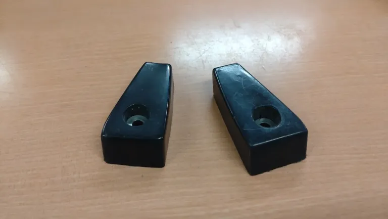
今回造ってみたのは、Z1R乗りなら1度くらいは紛失したことがある(?)、カウルエンドキャップ。
This time, I made a cowl end cap, which any Z1R rider might have lost at least once (?).
大したものじゃないのに、買うとものすごい高いパーツ。
It’s not much, but it’s very expensive to buy.
それに形も台形で単純だし。
And the shape is simple, like a trapezoid.
造る部品は、決まった。
The part to make is decided.
次に何をするかというと、採寸。
The next step is measuring.
完全コピーするんだったら、3Dスキャナというものがあるんだけど。
If you were making an exact copy, you’d use a 3D scanner.
今回は、パーツ各部の寸法を計測して、それをデータにしていく。
This time, I’ll measure the dimensions of each part and turn them into data.
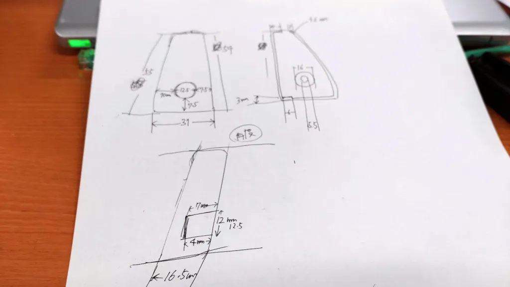
まずは、こんな感じで寸法を計測していく。
First, measure the dimensions like this.
正確に測りづらいところもあるけど、概算でも数値が出ないと始まらないので、とにかく何でもかんでも数字に置き換える。
Some parts are hard to measure accurately, but you need at least rough values to start, so convert everything into numbers.
カウルエンドキャップなんて単純な形なので、そんなに計測する箇所がないように見えるけど、実際やってみると案外あちこちの情報が必要になる。
The cowl end cap looks simple, but when you actually do it, you find you need measurements from various places.
最終的に使わなくなる箇所もあるかもしれないけど、測れる箇所は長さ、角度、とにかく測りまくる。
Some measurements might not be used in the end, but measure everything you can in terms of length and angle.
全部を計測したら、今度は3D CADソフトに図面を引いていく。
Once everything is measured, it’s time to draw the design in 3D CAD software.
いろいろな種類があるらしいけど、今回は仕事のからみで使えることになったSolid Works というソフトを使う。
There are various types, but this time I’ll use SolidWorks, which I can use through work.
ちなみに、これ普通に買うと余裕で100万円以上する高額商品!
By the way, this normally costs over a million yen!
とてもじゃないけど趣味で買えるものじゃない。
It’s not something you can buy for a hobby.
比較的安価なソフトとしては、Fusion360というのがあります。
A relatively inexpensive software is Fusion360.
とはいえ、年間で7万円くらいのサブスクリプションだから、ガチで使いこなす気概は必要かも。
However, it’s about 70,000 yen per year for a subscription, so you need to be serious about using it.
詳しいことについては、皆さんでググってほしい。
Please google for more details.
Solid WorksはおろかCADソフトを使ったのも生まれて初めてなんで(笑)。
It’s my first time using CAD software, let alone SolidWorks (lol).
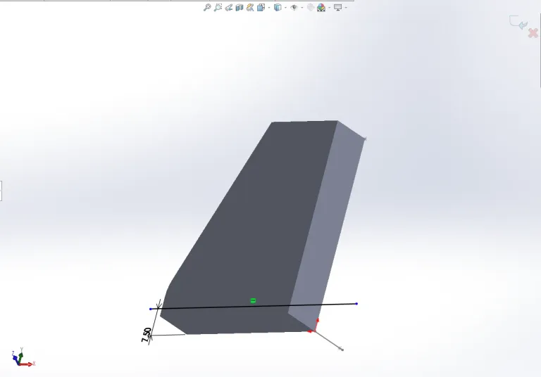
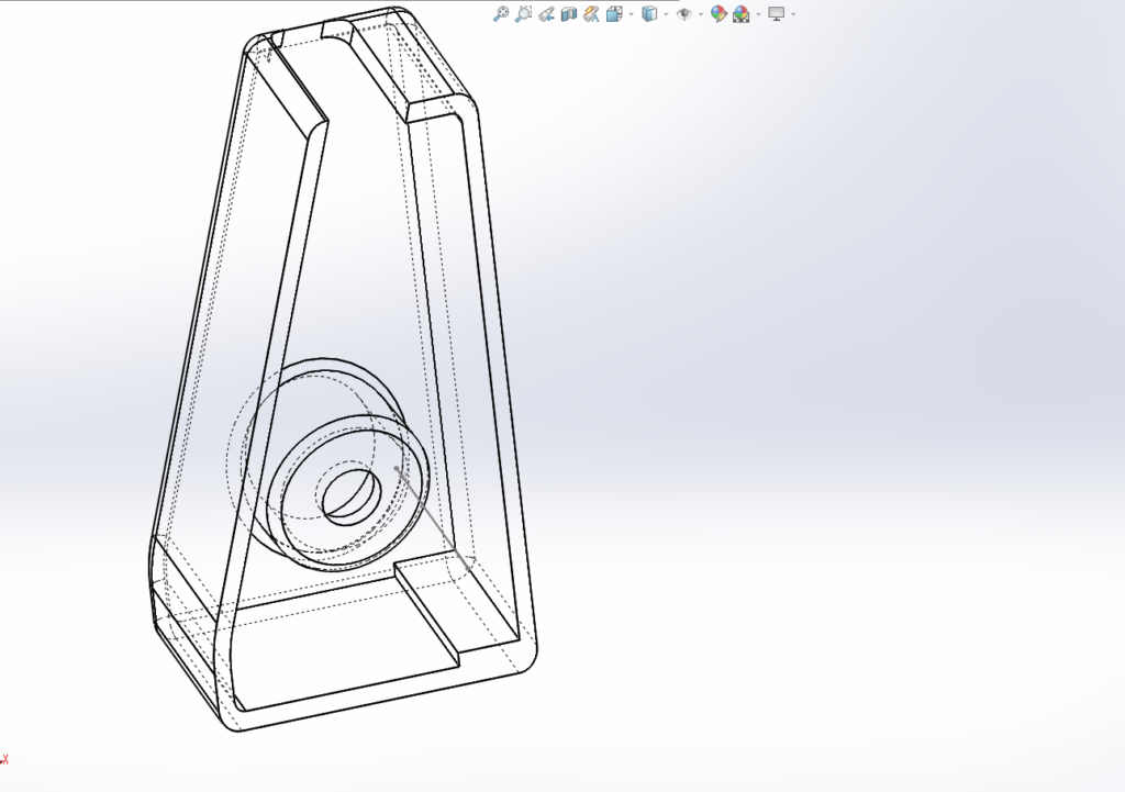
最初はこんな感じで大まかな線を引き、測った寸法を入れ込んでいく。
At first, draw rough lines and input the measured dimensions.
数値がおかしいと、見た目が全然違うものになったり、エラーが出るので分かりやすい。
If the numbers are wrong, the shape will look completely different or errors will occur, so it’s easy to spot.
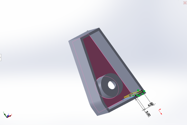
くりぬいたり、新しいパーツを足したりを繰り返して、だんだんと形にしていく。
Carve out parts, add new ones, and gradually shape it.
分かりやすくするために線画にしてみたり…
Use wireframes to make it easier to understand…
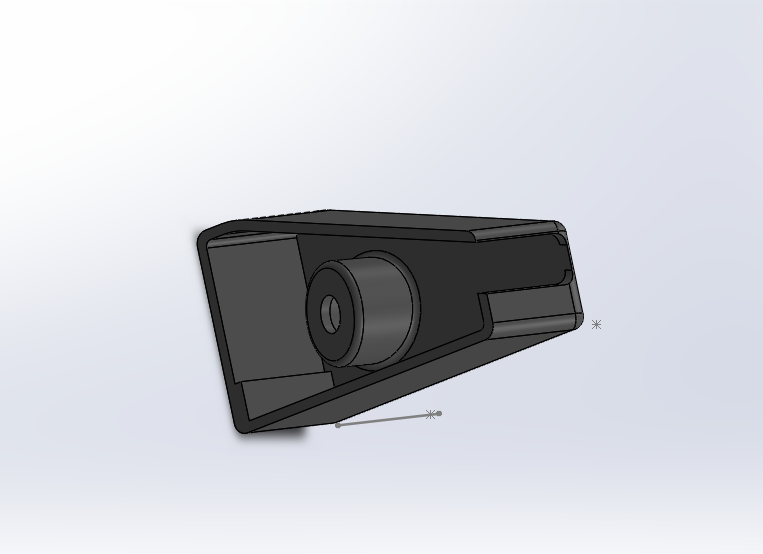
イメージをつかみたい時は、着色してやる。
Color it when you want to get a better idea.
マウスを操作すると、グリグリ動くので、全体的にイメージしやすい。
You can move it around with the mouse, making it easy to visualize the whole thing.
あとは職場にいる10年選手の達人を捕まえて、そっとカウルエンドキャップを渡します(笑)。
Then I hand the cowl end cap to a ten-year expert at my workplace (lol).
途中経過をかなりすっ飛ばしますが、ざっくりいうとこんな手順。
Skipping a lot of intermediate steps, here is a rough outline.
平面の形をつくる。
Create the flat shape.
厚みをつける。
Add thickness.
くりぬく。
Carve out parts.
ボルト穴用のパーツをつける。
Add parts for the bolt holes.
角を取ってみたり、微調整する。
Round the corners and make fine adjustments.
3Dプリンターにデータを転送する。
Transfer the data to the 3D printer.
出力。
Print it.
完成。
Done.
こう書くと、あっという間のようにも見えるけど、設計だけでも数時間を要したという…
It looks quick when written out, but it took hours just for the design…
達人はバイクのパーツに馴染みがなく、自分は設計のせの字も分からず、という二人三脚というより二人羽織状態(笑)。
The expert wasn’t familiar with bike parts, and I knew nothing about design, so it was more like a two-person performance than teamwork (lol).
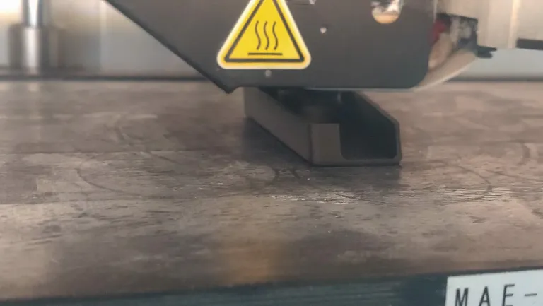
こんな風にノズルから樹脂が吹きつけられ、コンマ何ミリで樹脂が積み上げられていく。
The nozzle sprays resin like this, building it up in tenths of a millimeter.
薄紙を積み重ねていくような作業なので、こんな小さなパーツでも完成まで1時間以上を要する。
It’s like stacking thin paper, so even a small part takes over an hour to complete.
1個しか作っていないのは、画面と現物がどれくらい一致するか調べるため。
I made only one to see how well the screen matches the actual product.
なので、最初の2回は形状や質感などをチェックするだけで終わった。
So, the first two times were just to check the shape and texture.
Solid Works上では角を取ったつもりが、プリントしてみると角が強く残っている。
I thought I rounded the corners in SolidWorks, but they were still sharp when printed.
こうして現物にどんどん近づけていく。
Gradually, I got closer to the actual product.
解釈に自信がついたら、いよいよ左右同時にプリント。
Once confident in the design, I printed both sides simultaneously.
ちなみに3D CADの良いところが、鏡に映ったようにコピーできるので、コマンドひとつで反対側の図面が出来上がる。
The good thing about 3D CAD is that you can mirror the design, creating the opposite side with one command.
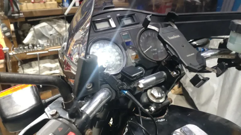
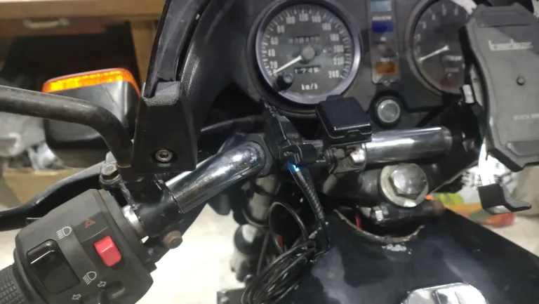
修正を重ねた3回目、いよいよ左右のパーツを出力して実機に取り付けてみる。
After three revisions, I finally printed both parts and installed them on the bike.
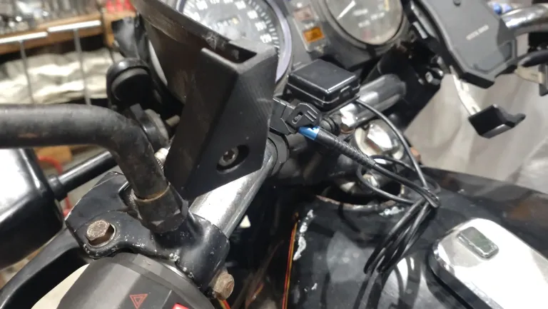
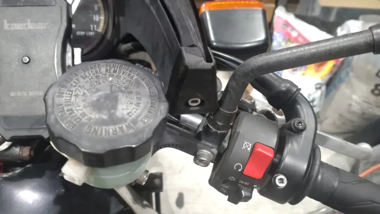
実際に取り付けてみたところ。
Here’s what it looked like when installed.
ボルト穴の出口の角度が現物と違っていて、クリアランスが大きくなってしまった。
The bolt hole exit angle was different from the actual part, resulting in larger clearance.
そして、切り欠きの位置も若干ズレている。
The notch position was also slightly off.
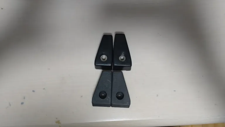
あと、実はカウルエンドキャップは台形のように見えて台形じゃない。
Also, the cowl end cap isn’t a true trapezoid as it appears.
辺の途中でRを描いている部分がある。
There’s a part that curves in the middle of the sides.
並べてみると、一目瞭然。
It’s obvious when placed side by side.
で、Rというか頂点をつけて外側に追い込んだラインを造って。
So, I added a curve and adjusted the outer line.
これで完成かと思ったら、追い込んだ時にSolid Worksのデータからフェアリングが収まる部分の切り欠き寸法が変わったり、トライ&エラーの繰り返し。
I thought it was done, but adjusting the curve changed the notch dimensions in SolidWorks, leading to more trial and error.
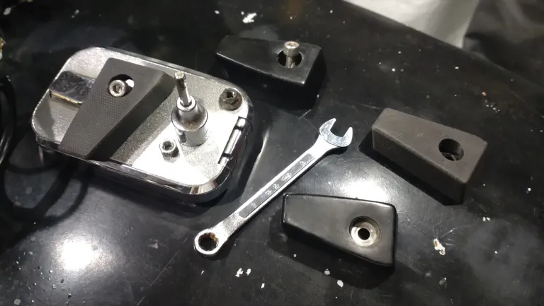
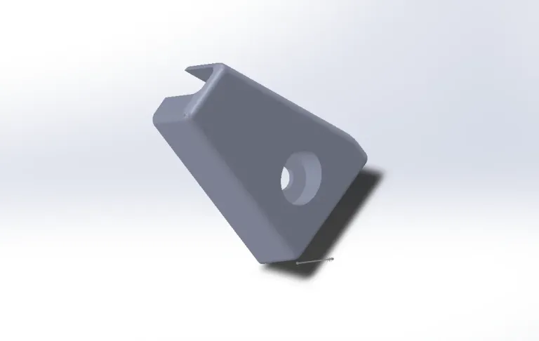
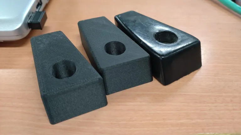
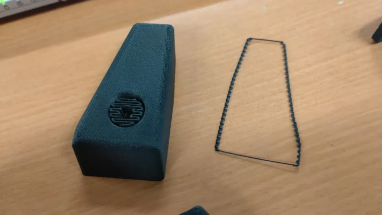
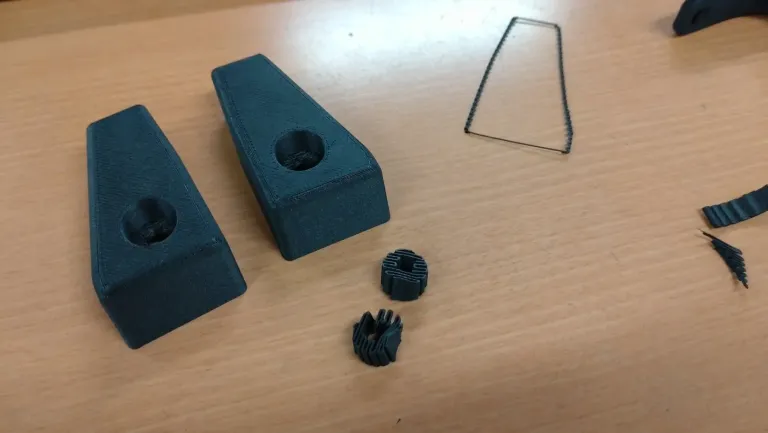
そして、4回目の出力で出来上がったのがコレ。
This is what I got on the fourth print.
オリジナルを忠実に再現しつつ、フェアリングが収まる切り欠き部分を少し狭くしたのは、よりフィットさせるため。
I faithfully reproduced the original while narrowing the notch slightly for a better fit.
いいんじゃないでしょうか!?
Isn’t it good!?
オリジナルと質感や形状が微妙に違うけど、謎めいていい感じ。
The texture and shape are slightly different from the original, but it has a nice, mysterious feel.
よもやこれが3Dプリンターから出力されたものだと気づく人はいないだろう。
No one would suspect this came from a 3D printer.
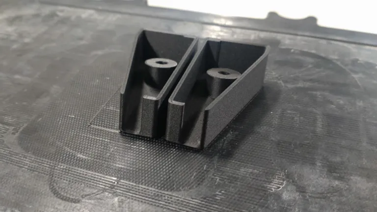
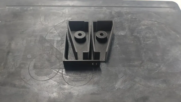
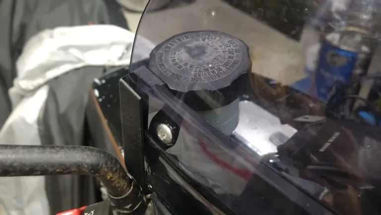
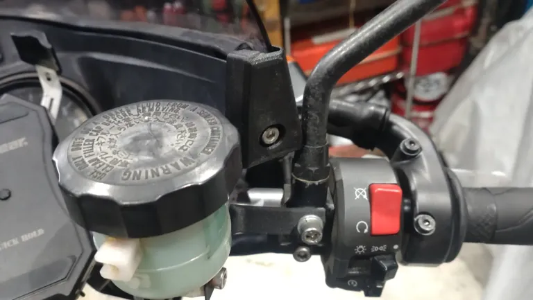
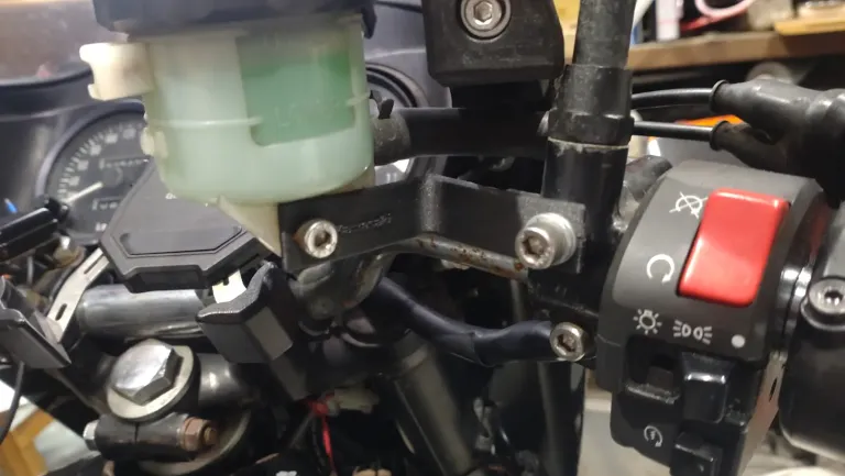
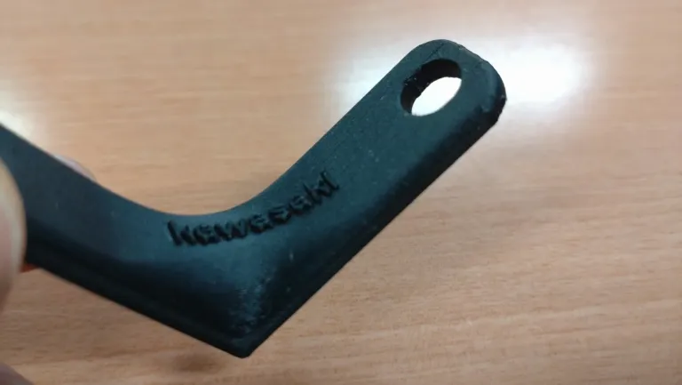
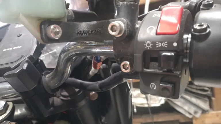
もう一点、つくったのがFブレーキのリザーバータンクを固定するブラケットというかステーというか、L字のアングル。
I also made an L-shaped bracket to secure the front brake’s reservoir tank.
これはもう簡単で、一筆書きで厚みのあるL字アングルの断面図を描き、それに厚みをつけ、ボルト用の穴を開口。
This was easy: draw a cross-section of the thick L-angle in one stroke, add thickness, and make bolt holes.
角を取って、折れ曲がってるところに少し厚みを持たせた。
Round the corners and add some thickness to the bent parts.
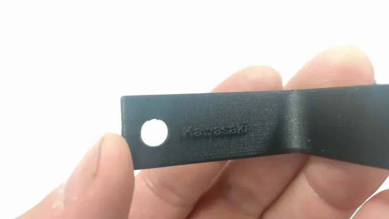
ついでにKawasakiの文字を浮き彫りにしてアクセントに。
I added the Kawasaki logo as an accent.

多分、手慣れた人なら10分以下で造れる。
Someone experienced could probably make it in less than 10 minutes.
3Dプリンターでも30分くらいじゃなかろうか?
Maybe about 30 minutes on a 3D printer?
樹脂製パーツで、極端に強度を必要としない部分は、こんな風にして作れるので良い時代になった。
It’s a good era when you can make resin parts that don’t need extreme strength like this.
ちなみに、3Dプリンターは金属を出力するものもあり、そちらではエンジンのシリンダーやエキパイなどを造ることも可能。
By the way, there are 3D printers that can output metal, which can make engine cylinders and exhaust pipes.
普段100円ショップだのホームセンターでパーツを造っているというのに、最新テクノロジーでのパーツ製作になってしまった(笑)。
Even though I usually make parts from 100 yen shop or hardware store items, I’ve now made parts with the latest technology (lol).
Additional Note
リザーバータンクを固定するL字アングル、鋼材と同じ厚みで製作したら剛性が全然弱かった。
The L-angle bracket for the reservoir tank had very weak rigidity when made with the same thickness as steel.
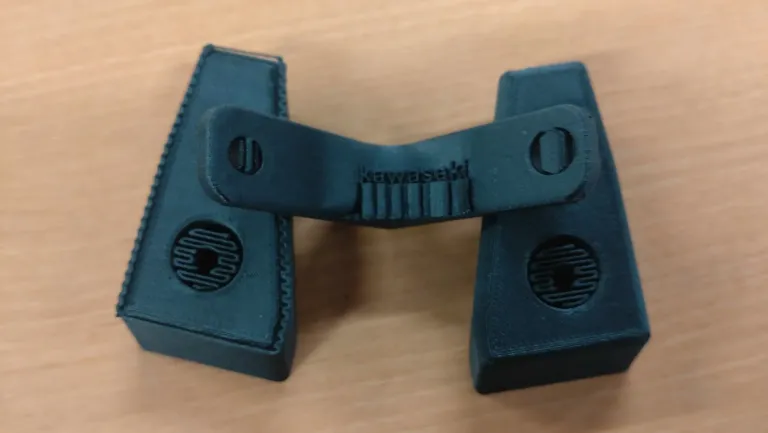
厚みを1.6mmから3.6mmに倍増、直角部分の内側を厚くRを盛ってやる。
I doubled the thickness from 1.6mm to 3.6mm and thickened the inside of the right-angle parts.
そこにKawasakiのロゴを押し出してスタイリッシュ…のつもり。
I embossed the Kawasaki logo there for a stylish look… or so I thought.
さらに大サービスで、材料の中にカーボン繊維を混ぜて出力したから、強度は鋼材以上(笑)。
As a bonus, I mixed carbon fiber into the material, making it stronger than steel (lol).
ハニカム構造で成型しているので、ある程度、厚みがないとイカンらしい。
It’s formed with a honeycomb structure, so it needs a certain thickness.
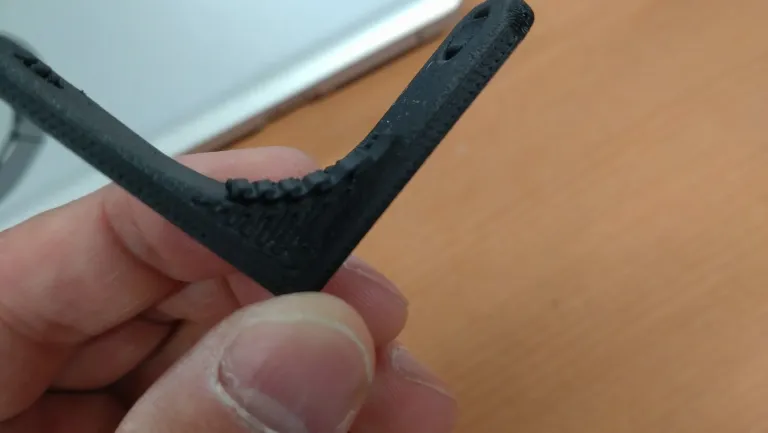
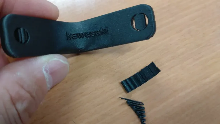
SNSにアップした時「カスみたいなのは何か」と聞かれたんだけど、これは3Dプリンターが出力する時に発生するサポート材。
When I posted it on social media, people asked what the “debris” was, and it’s the support material generated by the 3D printer.
3Dプリンターは自在に動くノズルが樹脂を少しずつ吹き付けるわけだが、形状によっては下がないものもある。
The 3D printer’s nozzle sprays resin bit by bit, but some shapes have no bottom.
たとえば「L」という文字は、下から樹脂を積層していくと形になる。
For example, the letter “L” forms by layering resin from the bottom.
しかし「T」の場合、上の「ー」状の部分は、空中に浮いているので、吹き付けると下に落ちてしまう。
But for the letter “T,” the top horizontal part is floating, so it would fall if sprayed directly.
なので、先に足場のようなパーツを成型して「ー」の部分を吹けるようにしている。
So, it first forms a scaffold-like part to support the top.
そしてカウルエンドキャップもフェアリングの部分、このクリアランスをもう少し詰められるのではないかと考え、隙間を3mmほど詰めてやった。
For the cowl end cap, I thought I could narrow the clearance of the fairing part, so I reduced the gap by about 3mm.
サポート材は指でペリペリはがれる場合もあるが、ボルト穴のように狭いところにしっかり成型されたモノはラジオペンチなどで無理やり引っ張り出す。
Support material can sometimes be peeled off by hand, but for tightly formed narrow areas like bolt holes, use pliers to pull it out.
いろいろな樹脂成型の経験があると「そんなに乱暴にして大丈夫?」と思うのだが、ラフにやっても大丈夫で、むしろ思い切って引っ張った方が良いらしい。
With experience in resin molding, I wondered if being rough was okay, but it’s actually better to pull forcefully.
分かりますか?この絶妙なクリアランス。
Can you see this perfect clearance?
ここがギリギリだと、ガタガタしなくなるというね…
Being this close means it won’t rattle.
オリジナルの形状とは違うかもしれないけど、これはこれで良いと思う。
It may be different from the original shape, but I think it’s good this way.
おそらく3Dプリンターを使ったカスタムは、今後増えていくと思う。
I think custom parts made with 3D printers will increase in the future.
カウルのような巨大な一発成型的なパーツは難しいかもしれないけど、手のひらに収まるようなパーツだったら選択肢も可能性も広がるんじゃないだろうか?
It might be difficult for large parts like fairings, but for palm-sized parts, the options and possibilities will expand.
コメント