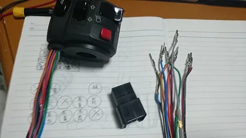
今回の獲物は、コレ。
This Time’s Prey: The Following.
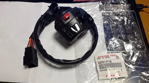
46091-0118
ハウジングアツシ(コントロール),LH
Housing Assembly (Control), LH
車種は、ZR1200DDF…ZRX1200 DAEGです。
For ZR1200DDF… ZRX1200 DAEG.
以前、ヤフオクで入手したGPz400Fのハンドルスイッチ(もちろん中古品)を流用していたのですが、随分とシオシオになってきたので交換しました。
I previously reused a handle switch from a GPz400F (of course, a used part) that I obtained on Yahoo! Auctions, but it has become quite worn out, so I decided to replace it.
今回は新品…ド新品です!
This time, it’s brand new… a completely new part!
が、実は1年前くらいに楽天のポイント使って購入したはいいけど、時間がなくて、ほったらかしにしていたものです。
However, I actually bought it with Rakuten points about a year ago but had no time to install it, so it was left untouched.
何しろ、大掃除していた時、PCラックの後ろから見つけたくらいだから、買った本人も忘れていたという(笑)。
I found it behind the PC rack during a big clean-up, so even I had forgotten about it lol.
旧いZなら、エストレアのハンドルスイッチ
For older Z models, the Estrella handle switch
46091-0122
が似合うという方々もいますが、価格が8,936円(2015年当時。部品はどんどん値上がりしていきますね)。
Some say it fits well, but it costs 8,936 yen (as of 2015. Prices for parts keep rising).
ダエグのスイッチは6,815円(2015年)だから、随分差があります。
The Daeg switch is 6,815 yen (2015), so there’s a considerable difference.
角Zなら、違和感もないでしょうということで、ダエグを選びました。
For the square Z, it doesn’t feel out of place, so I chose the Daeg.
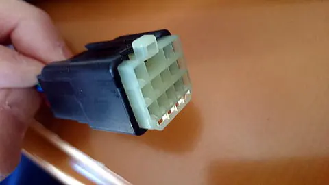
このままではメインハーネスには繋がらないので、要加工。
As it is, it cannot be connected to the main harness, so modifications are needed.
ちなみにカプラーは、スイッチ側が13P、メインハーネス側が9P。
The coupler on the switch side is 13P, and on the main harness side, it is 9P.
メインハーネス側のカプラーをいじるのは、失敗した時のリスクや、ポン付けスイッチを使う時がきたら面倒なのでやめておきます。
It’s better not to mess with the main harness side coupler because of the risk if something goes wrong and the hassle if I need to use a bolt-on switch later.
となれば、13Pをバラして9Pにするか…
So, should I disassemble the 13P and convert it to 9P…
ここで、変な色気が出ました。
At this point, I had a strange idea.
ポンづけに出来るよう、フィッティングパーツを作ってみよう!
Let’s make fitting parts to allow for a bolt-on!
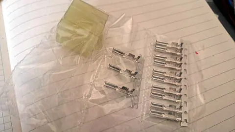
というわけで、いつものように配線資材を探します。
So, as usual, I started looking for wiring materials.
住友電装の13Pカプラーですが、メーカーのカタログからは見つけられず、資材屋さんの在庫から購入。
I couldn’t find the 13P coupler from Sumitomo Electric’s catalog, so I bought it from a parts supplier’s stock.
価格はそんなにしないのですが、こういうパーツは見つけるまでが一苦労。
The price isn’t that high, but finding these kinds of parts is quite a hassle.
都内や都内近郊に住んでいれば、アキバ観光ついでに配線屋巡りすればいいんでしょうけど。
If you live in or near Tokyo, you could visit wiring shops while sightseeing in Akihabara.
色は違うけど、ばっちりフィットします。
The color is different, but it fits perfectly.
どうせ裏に隠れてしまうパーツなので、気にしません。
Since it will be hidden behind, I don’t mind.
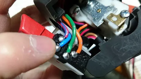
そしたら、スイッチケースをバラします。
Next, disassemble the switch case.
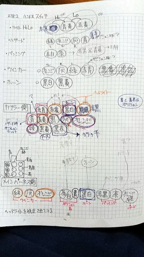
どのメーカーも、時代は変わっても配線の色は大抵同じものを使用しますので、それをメモしていく。
Most manufacturers use the same wiring colors even as time goes by, so take notes of them.
「機械に強い人はいいよね」と言われますが、ワタクシは理数系がまったく苦手で、高校時代は毎回のように赤点でした。
People say, “It’s great to be good with machines,” but I’m terrible at math and science; I used to get failing grades in high school.
小学校の時、科学クラブにいて、インターホンやラジオを作ったことがありますけど…ラジコンやプラモデルの延長なんでしょうね。
In elementary school, I was in the science club and made intercoms and radios… I guess it’s an extension of RC cars and plastic models.
まず、配線図をネットで拾います。
First, find a wiring diagram online.
ありがたいことに、車体の形式に配線図、とか入れて検索すると、見つかります。
Fortunately, you can find it by searching for the wiring diagram along with the model of the vehicle.
だいたい、それで掴めるはずですが、年式や仕様によって微妙に異なるケースもありますので、最終的には現物を確認しなければなりません。
That should give you an idea, but since there may be slight differences depending on the year and specifications, you need to check the actual parts.
例えば、灯火類でもホーンでも、ONにするということは、電気が流れる道が開通するわけですから、その状態を確認すればいいわけです。
For example, whether it’s lighting or the horn, turning it on means completing an electrical circuit, so you need to confirm that state.
「黒/白(ホーン)と黒/黄(アース)」が本当に正しいか知るためには、カプラーの先端に抵抗モードにしたテスターを当てます。
To verify that “black/white (horn) and black/yellow (ground)” are correct, use a tester in resistance mode on the end of the coupler.
この段階では、抵抗値が無限大、つまり電気は流れていないことになります。
At this stage, the resistance value is infinite, meaning no electricity is flowing.
で、その状態でホーンのスイッチを入れた時、抵抗値がゼロになればOK。
Then, if the resistance value drops to zero when you turn on the horn switch, it’s OK.
あとは、これをスイッチごとに繰り返していく。
Repeat this process for each switch.
いまの作業が出来る人なら、手間暇をかければゴールにたどり着きます。
If you can do this work, you can reach your goal with time and effort.
電気は駆動系のパーツと違って「パーツ同士の当たりをみる」とか「スムーズに回転するように組みつける」という技が要りません。
Unlike drive system parts, electrical parts don’t require skills like “checking the fit between parts” or “assembling to ensure smooth rotation.”
ちょっとだけ間違うということはなく、白黒ハッキリしているので、素人にも分かりやすいと思います。
There’s no such thing as slight mistakes; it’s clear-cut, so it’s easy for amateurs to understand.
もちろん、絶縁不良による火災には気をつけて作業しなければなりませんが。
Of course, you must be careful about fires caused by insulation failures.
で、とりあえず、カプラーのマッピングが終わったら、ポン付けのためのフィッティングパーツ作りを始めます。
Once the coupler mapping is done, start making the fitting parts for bolt-on installation.
これもまた、何処にどれがはまるのかをチマチマ作るだけなので…
This also involves carefully making parts to fit each position…
ハイ、こんな感じです。
Yes, like this.
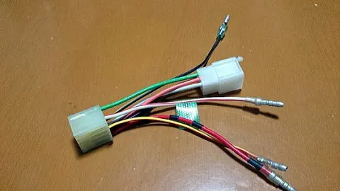
たまたま、メインハーネスを購入した時についてきた、何に使うか分からないカプラーとサブハーネスがあったので、そのまま利用します。
I happened to have some unknown couplers and sub-harnesses that came with the main harness, so I used them as is.
なので、線の色は適当。大事そうな部分だけ、目立つよう印をつけておきました。
So the wire colors are random. I marked only the important parts to make them noticeable.
13Pもあるくせに、結局、750FX/mk2のメインハーネス側に行くのは4系統だけ…!!
Although there are 13 pins, only 4 circuits connect to the main harness side of the 750FX/mk2…!!
ウィンカー3つ、ホーン1つ。あとは、ギボシで結線します。
Three for turn signals, one for the horn. The rest are connected with bullet terminals.
ZRX1200の場合、13Pの中に、上記4つのほか、ヘッドライト3つ、ポジション系2つ、クラッチ2つ、アース1つで合計12のハーネスがひとまとめになっているようです。
For the ZRX1200, besides the four mentioned above, the 13P includes three for headlights, two for position lights, two for the clutch, and one for the ground, totaling 12 harnesses.
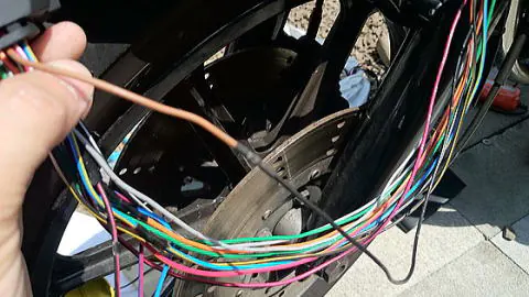
で、おそるおそる、点灯実験。
Then, nervously, I conducted a lighting test.
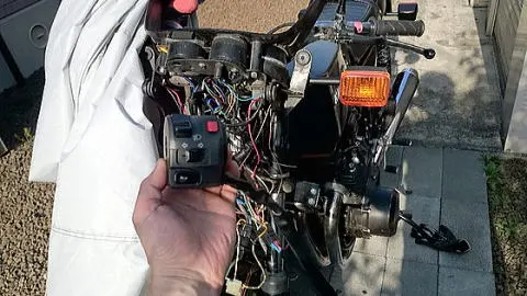
もちろん、この写真からは何も分かりませんが(笑)。
Of course, you can’t tell from this picture (laughs).
前後左右のウィンカーは問題なし。
The front and rear, left and right turn signals work fine.
ホーンも鳴ります。
The horn also works.
今回、一番のキモというか、何かの発射ボタンのようでカッコいいプッシュ式のハザードボタンも問題なく作動します。
This time, the key point is that the push-type hazard button, which looks like a launch button and is cool, works perfectly.
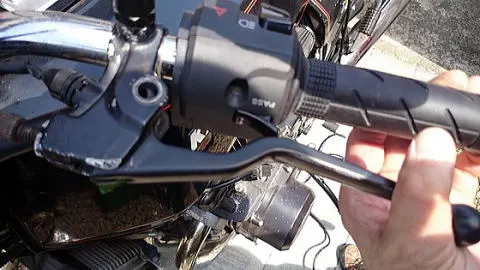
ただ、クラッチレバーのON/OFFハーネス。
However, the ON/OFF harness for the clutch lever.
せっかく根元から来て、カプラへ並走しているので、活かしたい。
Since it runs parallel to the coupler from the base, I want to utilize it.
でも、車体についているクラッチハーネスも欠品パーツですから、勢い余って切断…というわけにはいきません。
But since the clutch harness attached to the vehicle is also a missing part, I can’t just cut it off.
が、スターターロックアウトスイッチ(クラッチを握らないとエンジンが掛からない安全装置)は、現状問題がないうえ、さして重要なパーツでもないので、現状のまま活かすことに。
However, the starter lockout switch (a safety device that prevents the engine from starting unless the clutch is engaged) is currently not an issue and is not a particularly important part, so I decided to leave it as is.
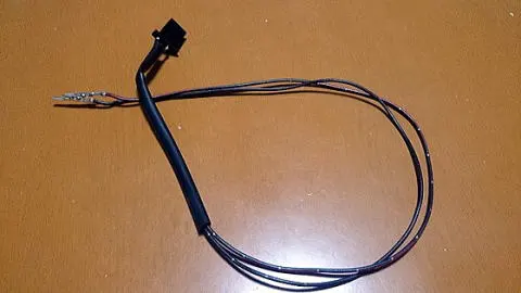
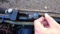
すると、スイッチ側についているハーネスとカプラーが邪魔になるわけです。
Then the harness and coupler attached to the switch side become an obstacle.
カプラーだけ抜いて、端子をカバーに押し込んでやろうとも思いましたが、余計なものがついているのは、あまりよろしくないので、抜き取ってしまいました。
I thought about just removing the coupler and pushing the terminals into the cover, but having unnecessary parts isn’t ideal, so I removed them.
いずれ、何かの役に立つ時がくるでしょう(笑)。
It will come in handy someday (laughs).
ということで、ボルトオンではなくなってしまいました(笑)。
So it didn’t end up being a bolt-on installation (laughs).
期待されていた方々(いるのか?)、すんません。
To those who were expecting it (if any), sorry.
まあ、こんな感じにひんむいてしまいました。
Well, I ended up stripping it like this.
どうせ、ひんむいたのですから、パッシングをちゃんと機能させてやることにしました。
Since I stripped it anyway, I decided to make sure the passing function works properly.
ZRX1200 ダエグの場合、ハイビームの回線は1系統。
For the ZRX1200 Daeg, the high beam circuit is a single system.
ライトをONにしていれば、パッシングも機能します。
If the lights are ON, the passing function also works.
が、Zの場合は、年代が古いので右ハンドルスイッチにライトのON/OFFがあります。
But for the Z, since it’s an older model, there is a light ON/OFF switch on the right handle.
このままだと、ライトをOFFにした状態でのパッシングは機能しません。
As it is, the passing function doesn’t work when the lights are OFF.
配線図を見れば分かるのですが、Zの場合、ハイビームは2系統。
Looking at the wiring diagram, the Z has two circuits for the high beam.
ディマースイッチとパッシングが分かれているのです。
The dimmer switch and the passing switch are separate.
とはいっても、別に難しく考える必要はありません。
However, there’s no need to overthink it.
メインハーネス側(9Pカプラ)の赤/黒と茶を短絡すれば、パッシングするので、ようするにパッシングスイッチからのハーネスと9P側をダイレクトに結んでやればいいのです。
If you short the red/black and brown on the main harness side (9P coupler), the passing will work, so basically, you just need to directly connect the harness from the passing switch to the 9P side.
パッシングスイッチの裏側には、赤/白と茶の配線が来ており、途中で
Behind the passing switch, there are red/white and brown wires, and along the way,
赤/白が赤/黒と。
Red/white connects to red/black.
茶が青/黄と結線されています。
Brown connects to blue/yellow.
なので、茶をバラして、9Pカプラ側の茶色と結合するようカプラに入れてやります。
So, separate the brown and insert it into the coupler to connect to the brown on the 9P coupler side.
ワタクシは、さきほどバラしたロックアウトの配線を流用しているので黒ですが、余分な配線と端子があれば色を統一した方が無難です。
I reused the lockout wiring I had separated earlier, so it’s black, but if you have extra wiring and terminals, it’s safer to unify the colors.
で、こんな風にしてテストしてやります。
So, test it like this.
ちなみに、赤/黒側はいじらなくてもOKです。
By the way, there’s no need to touch the red/black side.
スイッチ側では結線されていませんが、ヘッドライト側でつながっているので大丈夫です。
It’s not connected on the switch side, but it’s connected on the headlight side, so it’s fine.
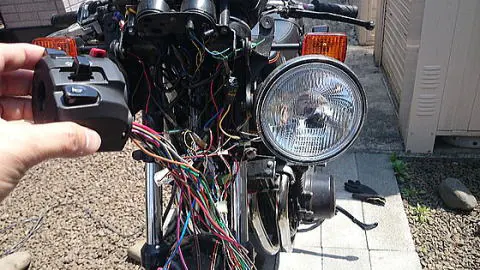
実験中の青空ガレージ。
Testing in the open-air garage.
ヘッドライトが外側についているのは、確認し易いため。
The headlight is placed outside for easy verification.
手を抜いてフェンダーの上に置いたりすると、ガシャンと落としたりするのです(笑)。
If you place it on the fender carelessly, it might fall with a crash (laughs).
ちなみに、ひんむいた黒いカバーは、上下を反対にして装着してやると使い勝手がいい。というのは、ロックアウトスイッチの配線を取り出すために、途中でキリコミが入っており、そこから水だのホコリだのが入るかもしれませんので。
By the way, if you install the stripped black cover upside down, it’s more convenient. This is because there’s a cutout for the lockout switch wiring, and water and dust might enter through it.
ライトとカウルに隠れる方に、そっちをもってきてやります。
So, bring that part to the side hidden by the light and cowl.
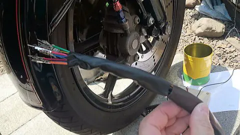
こんな感じです。
Like this.
はい、だんだん、読むのが飽きてたでしょう?
Yes, you’re probably getting bored of reading this, right?
で、どうなったのか聞きたいんでしょう?
And you want to know what happened, right?
ハイ、こんな感じですよ(号泣)。
Yes, this is how it turned out (tears).
『クラッチを握る度、パッシングするZ』に!!
It became a “Z that passes every time you pull the clutch”!!
当たり前だけど、このままじゃ使えないので、少し角度を変えて1cmちょいのところをかわしています(笑)。
Of course, it’s unusable like this, so I adjusted the angle to avoid it by about 1 cm lol.
まあ、これで妥協します。
Well, I’ll compromise with this.
本物はどういう風になってるのかな、と画像を探したら、最近のクラッチホルダーとかレバーって一回りくらい大きいんですよね。
When I looked for images of how the real ones are, I found that recent clutch holders and levers are about a size larger.
レバーも大きく曲がっているので、スイッチを取り囲むようにして、かわす感じでした。
The levers are also more curved, so they avoid the switch by wrapping around it.
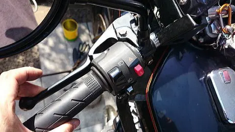
ライトとカウルを元に戻して、全体的な雰囲気を確認。
Restore the light and cowl and check the overall atmosphere.
個人的には、違和感がないのでよしとしましょう(笑)。
Personally, I think it looks fine without any discomfort (laughs).
シーズン序盤に間に合ったので良かったのですが…
I’m glad I made it in time for the beginning of the season…
◆◆ 付録 ◆◆
◆◆ Appendix ◆◆
ようするに、手順はこんな感じです。
In short, the procedure is as follows:
1.スイッチとカプラー(配線)の解析。
Analyze the switch and coupler (wiring).
2.フィッティングパーツの製作。
- Manufacture the fitting parts.
3.取り付け。
- Installation.
1については、13Pカプラの配線図が落ちてなかったので、スイッチを分解、テスターを1本ずつ当てて解析しました。
For 1, since I couldn’t find a wiring diagram for the 13P coupler, I disassembled the switch and analyzed it with a tester one by one.
ヘッドライトHi/Lo(ディマースイッチ)
Headlight Hi/Lo (Dimmer switch)
赤/黒 Hi
Red/Black Hi
青/黄
Blue/Yellow
赤/黄 Lo
Red/Yellow Lo
ハザード&ウィンカー
Hazard & Turn Signals
緑 Leftウィンカー
Green Left Turn Signal
橙 リレー
Orange Relay
灰 Rightウィンカー
Gray Right Turn Signal
青 ポジション 消灯
Blue Position Off
青/赤 同上
Blue/Red Same as Above
パッシング
Passing
赤/白 → 赤/黒
Red/White → Red/Black
茶 → 青/黄
Brown → Blue/Yellow
※途中で合流
*Merge midway
ホーン
Horn
黒/白
Black/White
黒/黄 アース
Black/Yellow Ground
コメント